VGA video card
building a VGA video card from scratch—because who doesn’t love turning a bunch of wires and chips into something that actually works?
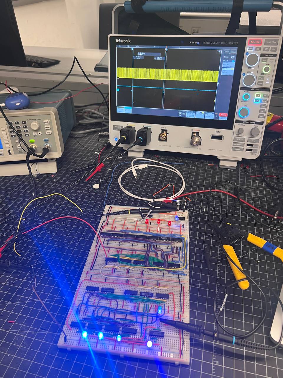
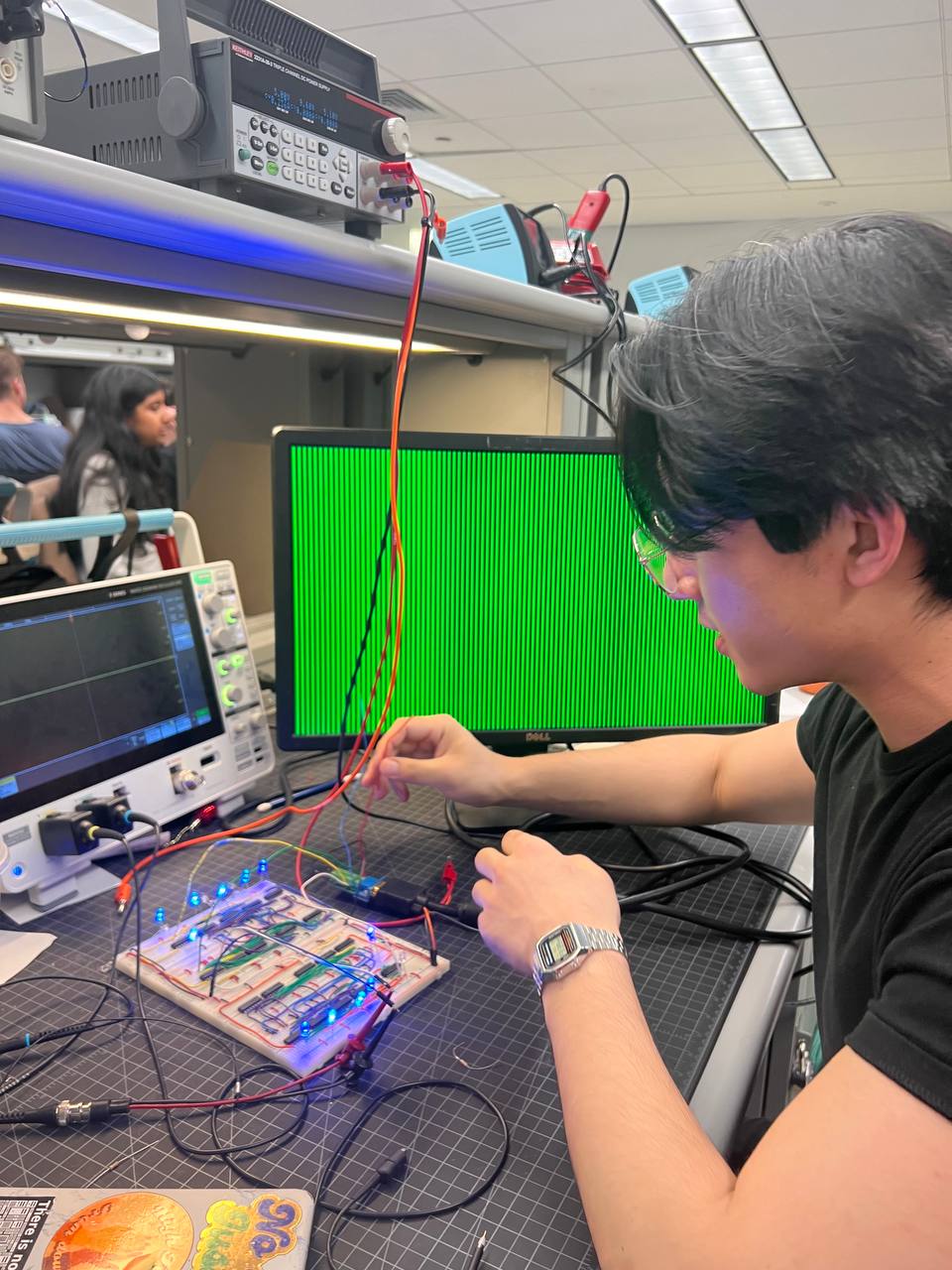
Because I cannot afford a real high-tech graphics card from a real hardware company, I built a custom VGA video card from scratch using digital logic components on breadboards with my partner Han Lee. This project allowed me to explore video signal processing fundamentals while creating something that produces real visual output on a standard monitor.
(I don’t know who thought it was a good idea with the amount of connections that it has but it actually works). I know it does not look as impressive with the pictures that we have of the lines on the screen, but this CAN produce ANY images you want if you control each pixel with certain color combinations and videos as a result.
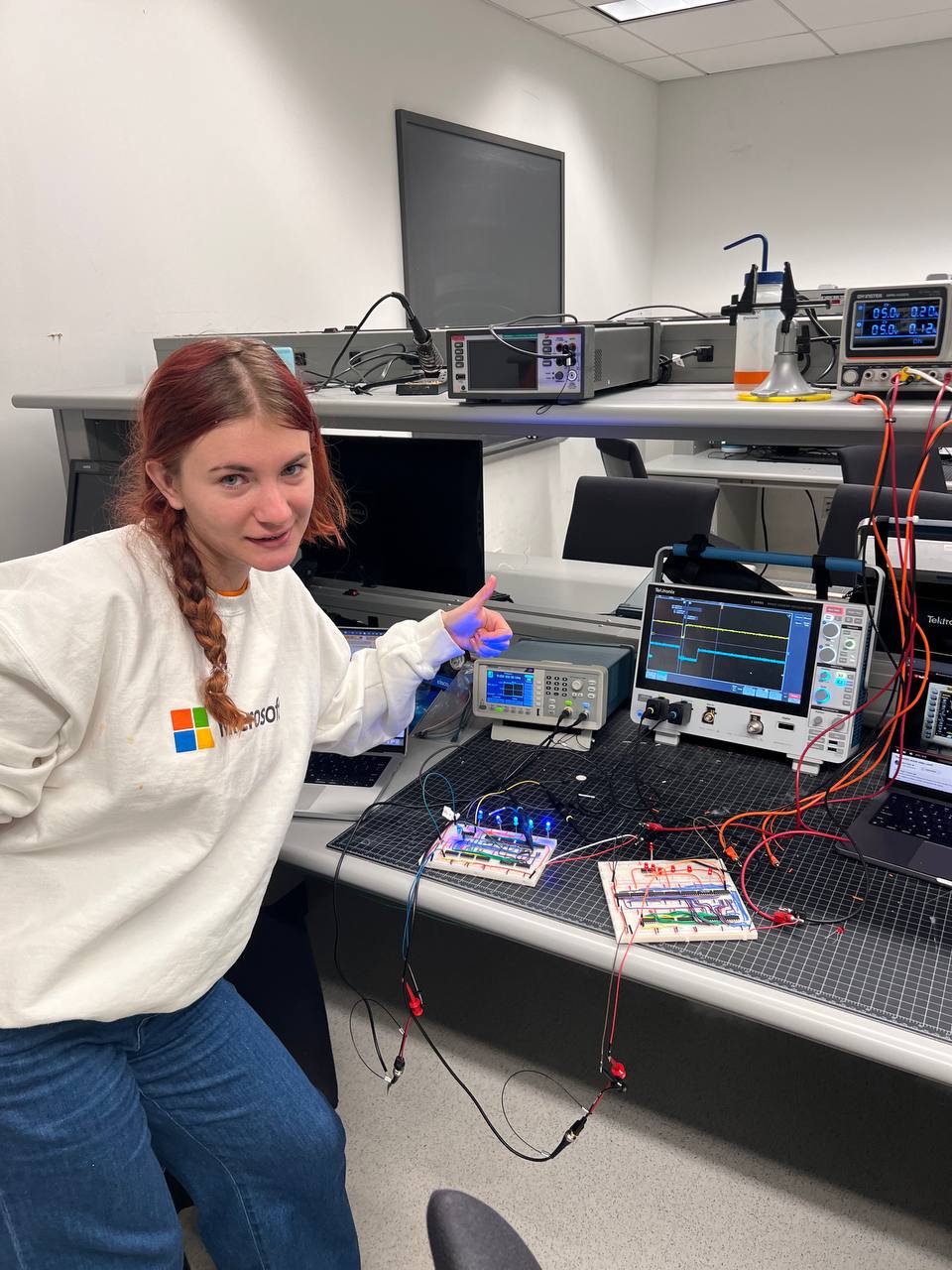
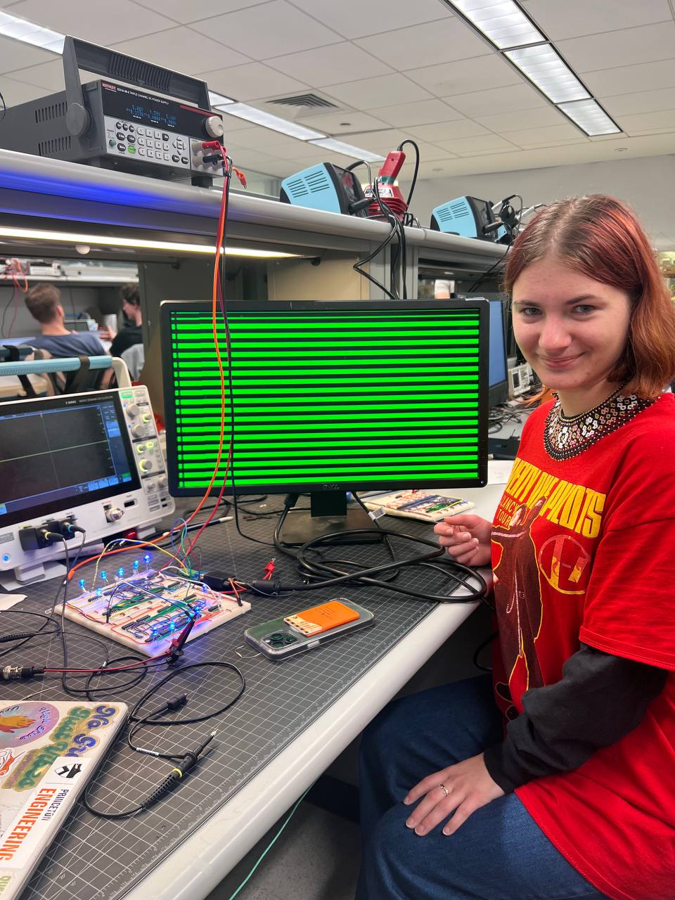
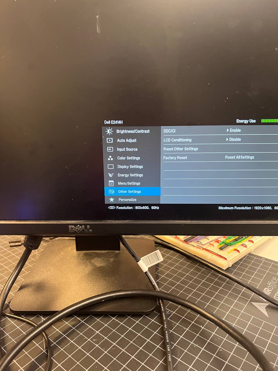
The goal was to generate a proper 800x600 SVGA video signal that a standard monitor could recognize and display. This required precise timing for both horizontal and vertical synchronization signals, which had to be generated using only basic digital logic components.
Rather than using modern microcontrollers, we took the more challenging route of building the system with discrete components:
- Used binary counters to track position within the video frame
- Created logic circuits to generate proper sync signals
- Built separate boards for horizontal and vertical synchronization
- Designed the system to handle signal timing with precision down to microseconds
We did build this like real electrical engineers: used oscilloscopes to measure precise timings and captured electrical wave signals of our components and function generators to test each component along the way, built diagrams for all the components before building them using KiCad.
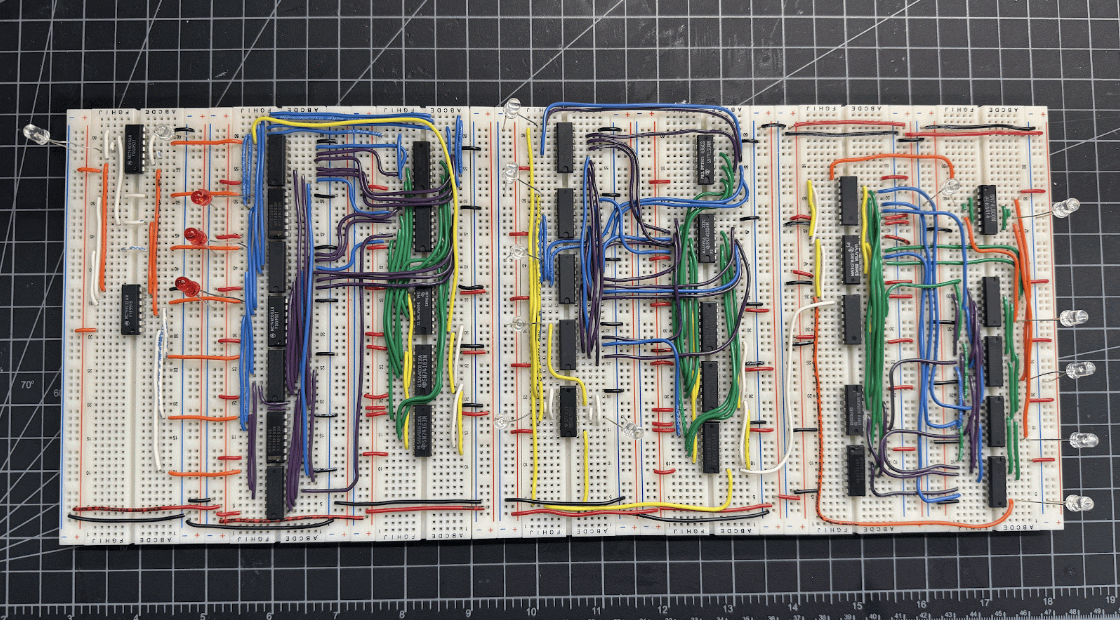

The Great Clock Debacle
No good engineering story is complete without a crisis, and this one arrived in the form of clock timing. Originally designed for a 40MHz clock (as is proper for SVGA signals of this resolution according to the specs online), I discovered that the clock we ordered was not a real clock, but simply a quartz oscillator that is just a part of a clock and we only had a signal function generator that got us up to 29MHz.
After a brief existential crisis, we redesigned the system for a more leisurely 10MHz pace with a smaller pixel count. The result was not much different from the one expected, but for higher precision images would be noticeable.
Here are some resources that we used:
- Ben Eater guide to this complicated world: https://eater.net/vga
- VGA connector pinout: https://pinoutguide.com/Video/VGAVesaDdc_pinout.shtml
- VGA signal timings: http://www.tinyvga.com/vga-timing